Beauty Unlocked
Homebrew Coil Winder Makes Toroids A Snap To Wind
Jun
Winding a toroid by hand is one of those jobs that looks peaceful until you actually try it. At first, it feels simple: take a donut-shaped magnetic core, pass magnet wire through the center, repeat until the turn count is right, and enjoy your beautifully homemade inductor or transformer. Then reality kicks in. The wire kinks, the turns bunch up, your fingers start negotiating for better working conditions, and somewhere around turn 47 you begin questioning your life choices.
That is exactly why a homebrew coil winder for toroids is such a satisfying machine. It takes a task known for being fiddly, repetitive, and slightly rude to human patience, then turns it into a smoother, more controlled process. Instead of manually threading a long tail of wire through the core over and over, the winder uses a shuttle or winding ring to carry wire through the toroid while the core is rotated to distribute turns evenly. The result is cleaner winding, better repeatability, and fewer moments where the builder mutters at copper wire like it personally started the argument.
The idea behind the project is wonderfully practical: build a simple mechanism that passes a small supply of magnet wire through the toroid’s center while rotating the core so each turn lands in the right place. It is a garage-friendly solution to a real electronics problem, and it captures the best part of homebrew engineering: solving a tiny annoyance with a clever machine that feels like it should have existed on every workbench already.
Why Toroids Are Worth the Trouble
Toroidal cores are popular in electronics because their shape gives them useful magnetic advantages. A toroid is a closed magnetic path, which means much of the magnetic flux stays inside the core rather than spraying into nearby circuits like an electromagnetic confetti cannon. That makes toroidal inductors and transformers attractive for power supplies, RF circuits, filters, current sensors, audio equipment, and compact high-current designs where efficiency and low electromagnetic interference matter.
Compared with many open-core shapes, toroids can offer high inductance in a relatively small volume. Their round geometry allows windings to wrap around the full core, creating a compact component with good magnetic coupling. When used correctly, toroids can reduce stray fields, improve efficiency, and help keep sensitive circuits from picking up noise. In practical terms, that means your circuit is less likely to behave like it just drank three cups of gas-station coffee.
But the same shape that makes toroids electrically appealing also makes them mechanically annoying. Unlike a bobbin or solenoid form, a toroid has no open side. Every turn must pass through the hole. If the wire is long, each pass means pulling the full wire length through the center. If the wire is thick, stiff, or enameled, the job becomes even less glamorous. Add multiple windings, bifilar wire, or a high turn count, and the humble toroid becomes a tiny copper obstacle course.
The Basic Problem: Human Hands Are Not Great Coil Machines
Hand-winding works fine for small jobs. A dozen turns on a little ferrite bead? No problem. A quick RF choke? Easy enough. But once the project requires a higher turn count or consistent spacing, hand-winding starts to show its limits. The wire may overlap. The tension changes. Turns crowd together on one side of the core. Counting becomes harder, especially when the phone rings, the dog barks, or someone asks whether you have “almost finished that little electronics thing.”
Uneven winding is more than an aesthetic issue. Spacing, layering, wire tension, and turn placement can influence inductance, leakage fields, parasitic capacitance, and repeatability. For many hobby projects, a slightly messy winding may still work. For filters, transformers, RF projects, and power electronics, however, consistency matters. A neatly distributed single-layer winding can help the finished component behave closer to the intended design.
This is where a homebrew toroid winder earns its keep. Instead of making the builder pull long wire lengths through the toroid repeatedly, the winder carries a smaller supply of wire around the core. The operator can focus on turn count, spacing, and tension while the machine handles the repetitive motion. It is not magic. It is better than magic: it is mechanical leverage.
How a Homebrew Toroid Coil Winder Works
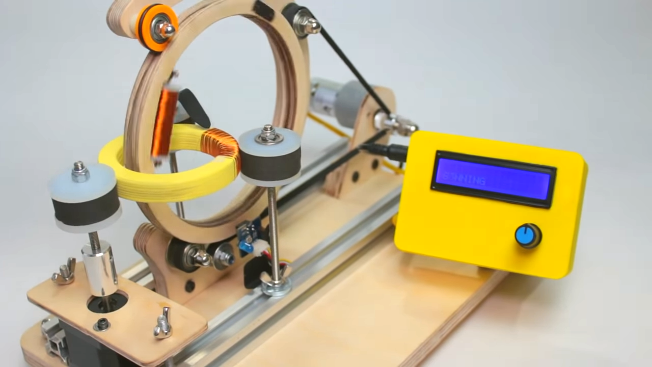
The core concept is simple. A winding ring, shuttle, or split hoop holds magnet wire and passes through the center of the toroid. Because the toroid is a closed ring, the shuttle itself must open or split so it can be loaded through the core. Once the shuttle is in place, it rotates around the toroid’s cross-section, laying wire onto the core one turn at a time.
At the same time, the toroid is usually rotated slowly so the turns spread around the circumference. This second motion is important. If the shuttle keeps wrapping wire in the same location, the winding piles up into a lumpy copper traffic jam. Rotating the toroid allows the wire to land evenly around the donut. The machine therefore performs two related jobs: feeding the wire through the center and indexing the core so each turn finds a sensible place to live.
Main Parts of a DIY Toroid Winder
A practical homebrew version can be made from plywood, plastic, 3D-printed parts, bearings, screws, belts, gears, or whatever respectable junk is currently hiding in the shop drawer. The design can vary, but most toroid winders include the following parts:
- A split winding ring or shuttle: This carries a short supply of magnet wire through the core.
- A toroid holder: This supports the core while allowing it to rotate.
- A drive mechanism: This may be hand-cranked, motorized, geared, or belt-driven.
- A wire guide: This helps control placement and prevents scraping the enamel insulation.
- A tensioning method: This keeps wire snug without stretching or damaging it.
- A turn counter: This may be mechanical, electronic, optical, magnetic, or simply a careful operator with a notebook and trust issues.
The beauty of the homebrew approach is that the winder does not need to be industrial-grade to be useful. Even a simple hand-powered build can make toroids easier and more consistent. A more advanced version can use stepper motors, an Arduino or similar controller, optical sensors, and programmable turn counts. But the core principle remains the same: carry wire through the toroid efficiently and place it evenly.
Why the Split Ring Is the Clever Part
The split winding ring is the trick that makes the whole thing practical. A normal closed ring cannot be inserted through a toroid after the core is already present. By adding a slit, hinge, removable section, or latch, the builder creates a shuttle that can open, pass through the toroid, and close again. It is a small mechanical idea with a big payoff.
Once closed, the ring holds a supply of wire and can rotate continuously through the core. This avoids the biggest annoyance of hand-winding: dragging the entire wire length through every time. Instead, wire is loaded onto the shuttle, then transferred to the toroid as the shuttle moves. It is the same basic logic used in many commercial toroidal winding machines, scaled down into a home workshop format.
Wood, especially plywood, can work surprisingly well for a prototype because it is easy to cut, drill, sand, and modify. Plastic or 3D-printed parts can be smoother and more precise. Metal can be durable but must be used thoughtfully around magnetic parts and electrical insulation. The best material is the one that makes the machine stiff enough to hold alignment but smooth enough not to damage the wire.
Even Winding Is Not Just for Looks
A neat toroid looks professional, but appearance is only part of the story. Evenly spaced windings help produce more predictable electrical behavior. If turns are bunched in one area, the coil may show different leakage, capacitance, and inductance characteristics than expected. In RF work, messy winding can shift performance in ways that are not obvious until the circuit is tested. In power electronics, poor winding can contribute to heat, noise, or unwanted coupling.
For many toroidal inductors, every pass through the center of the core counts as one turn. That sounds easy, but high turn counts can still become confusing. A turn counter helps prevent mistakes, especially when winding dozens or hundreds of turns. A homebrew winder can include a magnet and reed switch, an optical interrupter, a microswitch, or a simple mechanical counter. The exact method matters less than having a reliable way to track progress.
Wire tension also matters. Too loose, and the winding shifts or looks sloppy. Too tight, and the wire insulation may scrape, stretch, or suffer damage at the edges of the core. Many builders wrap the core with tape before winding to protect the wire and improve mechanical stability. Smooth edges, rounded guides, and gentle tension can make the difference between a durable component and a copper heartbreak pastry.
Choosing Wire and Core Materials
A coil winder is only part of the equation. The core and wire must match the job. Ferrite cores are often used for high-frequency transformers, RF chokes, EMI suppression, and signal applications. Powdered iron cores are common in RF inductors, filters, and energy-storage applications where stable behavior and specific permeability values are useful. Other materials, including sendust, Kool Mu, high-flux, and nanocrystalline cores, may be used in specialized power designs.
Wire gauge depends on current, resistance, available window area, frequency, and heating. Fine magnet wire is easy to wind but has higher resistance and lower current capacity. Thick wire handles more current but is harder to bend around a small toroid. Litz wire can reduce skin-effect losses at higher frequencies, though it is more expensive and more delicate to handle. For many hobby builds, standard enameled copper magnet wire is the practical choice.
Core size matters too. A larger toroid offers more room for turns and thicker wire, but it takes more space on the board. A smaller toroid saves room but can be frustrating to wind and may saturate sooner in power applications. The designer must balance inductance, current, frequency, losses, temperature rise, and physical size. The coil winder does not remove the need for design calculations, but it does make the manufacturing step less painful.
Manual vs. Motorized Toroid Winders
A manual winder is often the best starting point. It is simpler, cheaper, and easier to debug. A crank gives the builder direct feedback. If the wire snags, the hand feels it immediately. If the toroid slips, the operator can stop before anything dramatic happens. Manual machines are excellent for hobbyists who wind occasional inductors, transformers, baluns, and chokes.
A motorized winder becomes useful when repeatability and speed matter. Stepper motors can control both shuttle motion and toroid rotation. A microcontroller can track turns, adjust speed, pause at a preset count, or coordinate motion between axes. This is especially helpful for small production runs or complex coils where consistency matters. However, automation adds complexity. Motors need drivers, power supplies, firmware, limit switches, and mechanical alignment. In other words, the machine begins as a coil winder and quietly evolves into a small robot with copper hobbies.
The best design depends on use. A ham radio builder winding the occasional toroid for an antenna tuner may love a hand-cranked version. A maker producing repeated inductors for a power converter experiment may prefer a motorized setup. A classroom or lab might benefit from a hybrid design: manual loading, motorized counting, and adjustable speed.
Practical Design Tips for Building One
Start with the toroid sizes you actually use. A winder built for large power transformer cores may be clumsy with tiny RF toroids, and a small delicate machine may not appreciate heavy copper wire. Measure the outer diameter, inner diameter, and thickness of your common cores before designing the shuttle and holder.
Keep the wire path smooth. Any sharp corner can scrape enamel insulation, and damaged enamel can lead to shorted turns. Sand wooden parts carefully, round plastic edges, and consider adding low-friction guides. If the wire rubs against the shuttle, polish the contact area or add a small sleeve. Copper wire remembers insults.
Make the shuttle easy to load. If loading wire onto the ring takes longer than winding the toroid, the design needs improvement. A removable section, simple latch, or openable ring can save time. The shuttle should hold enough wire for the job but not so much that it becomes bulky and hard to pass through the core.
Add a simple tension control. Felt pads, spring-loaded guides, adjustable friction washers, or a light drag mechanism can work. The goal is steady tension, not a wrestling match. The wire should settle firmly against the core without crushing insulation or flexing the machine.
Build in visibility. The operator should be able to see where the wire is landing. A beautiful machine that hides the winding area is like a toaster with no slot: technically interesting, practically suspicious. Good visibility makes it easier to correct spacing before mistakes become buried under later turns.
Common Mistakes When Winding Toroids
Overlapping Turns
Overlapping may be unavoidable in multi-layer windings, but accidental overlap in a single-layer winding is usually a sign of poor spacing or tension. It can increase parasitic capacitance and make the component less predictable. A winder should help avoid this by coordinating toroid rotation with shuttle passes.
Losing Count
Counting by memory is heroic, but not always wise. A missed turn can change inductance. An extra turn can also matter, especially in RF circuits. Use a counter, mark progress, or build an electronic sensor into the machine.
Ignoring Core Edges
Some toroids have rough edges. Tape, sleeving, or careful smoothing can protect enamel. Never assume the core is wire-friendly just because it looks harmless. Tiny rough spots can do tiny terrible things.
Using the Wrong Core
A winder can make a coil neat, but it cannot make the wrong material behave correctly. Ferrite, powdered iron, and other core materials are not interchangeable. Choose material based on frequency, current, inductance, saturation, and loss requirements.
Where Homebrew Toroid Winders Shine
A DIY toroid winder is especially useful for radio projects, switching power supplies, current transformers, EMI filters, audio transformers, baluns, impedance matching networks, and experimental inductors. It also helps when rebuilding vintage gear or making custom parts that are difficult to buy off the shelf.
For amateur radio operators, toroids appear in antenna tuners, filters, transformers, common-mode chokes, and matching networks. For power electronics builders, toroidal inductors can appear in buck converters, boost converters, inverters, and noise filters. For educators, a visible coil winder can demonstrate electromagnetic principles in a way that is far more memorable than a chalkboard equation alone.
There is also a deeper maker satisfaction here. A homebrew coil winder is a tool that makes other tools and components possible. It is a machine that expands the builder’s ability to prototype. Once it exists on the bench, custom magnetics feel less intimidating. Suddenly, winding a toroid is not a dreaded final boss. It is just another step in the build.
Real-World Experience: What Building and Using One Teaches You
The first lesson from using a homebrew toroid winder is that the machine does not need to be perfect to be useful. A slightly wobbly prototype can still teach more than a dozen sketches. Once the shuttle begins passing through the core, the important details become obvious: where the wire rubs, where the toroid slips, where tension changes, and where the operator naturally wants more room for fingers. Good tools are designed on paper, but great shop tools are improved after they misbehave in public.
One practical experience is learning how much wire to load onto the shuttle. Too little wire means stopping halfway through the winding, reloading, and trying to resume without creating a messy joint or uneven tension. Too much wire makes the shuttle heavy and awkward. The sweet spot depends on wire gauge, toroid size, and turn count. After a few coils, most builders develop a feel for estimating wire length, then add a little extra because copper has a talent for proving optimism wrong.
Another lesson is that tension should be gentle and consistent. Beginners often pull too hard because they want a tight, tidy coil. Unfortunately, too much tension can scrape insulation, especially near core edges. A better approach is to let the wire settle snugly while guiding it into place with light pressure. If the core is taped before winding, the wire usually behaves better and the finished coil feels more secure.
Turn spacing becomes easier with practice. At first, the operator may stop constantly to nudge turns apart. Later, the motion becomes rhythmic: feed, rotate, guide, check, repeat. A good winder supports this rhythm. The machine should not fight the builder. The crank should move smoothly, the shuttle should clear the core without scraping, and the toroid holder should rotate predictably. When all of that comes together, winding becomes almost relaxing. Almost. Let us not oversell it; magnet wire still has a personality.
Using a winder also teaches respect for planning. Before winding, it helps to know the required number of turns, target inductance, wire gauge, core material, and lead orientation. Mark the start lead clearly. Decide whether the winding should cover the whole core or only a sector. Check whether the circuit needs a single winding, bifilar winding, tapped winding, or multiple isolated windings. Once the wire is on the core, changes are possible, but they are not always fun. Unwinding a toroid is basically electronics archaeology with more sighing.
Testing is part of the experience too. After winding, measure inductance if you have an LCR meter. Check continuity. Inspect for scraped enamel, crossed turns, and loose sections. For transformers, verify winding polarity and turns ratio. For power applications, watch temperature during operation. A coil that looks beautiful can still perform poorly if the design assumptions were wrong, and a plain-looking coil can work wonderfully if the material, turns, and layout are correct.
The biggest reward is confidence. Many hobbyists avoid toroids because they seem fussy or mysterious. A homebrew winder removes much of that fear. It turns the process into a repeatable workshop operation. Once you can wind one clean toroid, you can wind another. Then you can experiment with different cores, different wire, different turn counts, and different circuit ideas. That is the real value of the tool: it lowers the friction between imagination and hardware.
Conclusion
A homebrew coil winder makes toroids a snap to wind because it solves the most annoying part of the job: repeatedly threading wire through a closed magnetic core while trying to keep everything neat, counted, and evenly spaced. With a split shuttle, a rotating core holder, smooth wire guides, and steady tension, a simple DIY machine can produce cleaner toroidal inductors and transformers with less frustration.
For makers, radio builders, electronics hobbyists, and power supply experimenters, this kind of tool is more than a convenience. It opens the door to custom magnetic components, faster prototyping, and better control over the parts that shape circuit performance. It also proves a classic workshop truth: sometimes the best way to finish a project is to build another tool first.
